Stepan ParunashviliTwitterInstantBooksFitness
Simulating RAM in Clojure
“Computers are all made out of logic gates”. We’ve heard that saying before. We also have a sense that logic gates are very simple machines, analogous to light switches even. This raises the question: how exactly do kind-of-light-switches come together to form computers? How does “storing a variable” or “calling a function” translate into logic gates going on or off?
On a journey to answer that question, I discovered J Clark Scott’s excellent book “How do It Know?”. He starts with NAND gates and takes you on a journey to build a computer using them.
I liked his book so much that I took his schematic for RAM, and simulated it in Clojure. In this essay, I’ll guide you through doing just that: we’ll simulate NAND gates, and use about 14 thousand of them to build 256 bytes of RAM.
Going through this simulation ingrained an “aha” feeling in me: watching 14 thousand little machines chug away makes you feel that whoever uses a computer is a wizard. A wizard with an army of millions of machine servants doing billions of little jobs for them every second. I hope it gives you the same feeling. 🙂
Pre-requisites
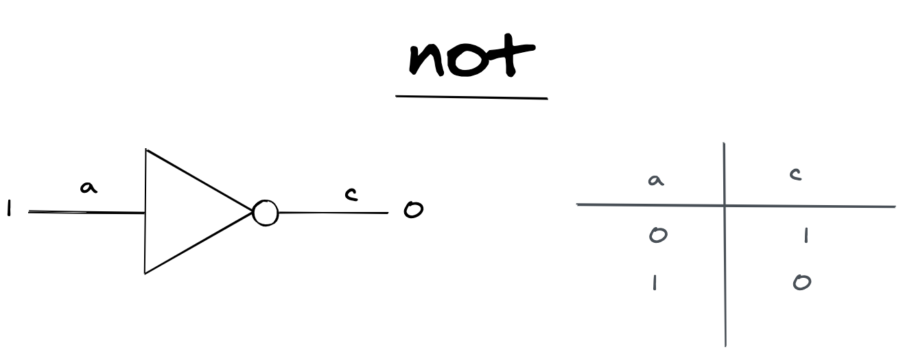
To grok this essay, you need to understand this picture:
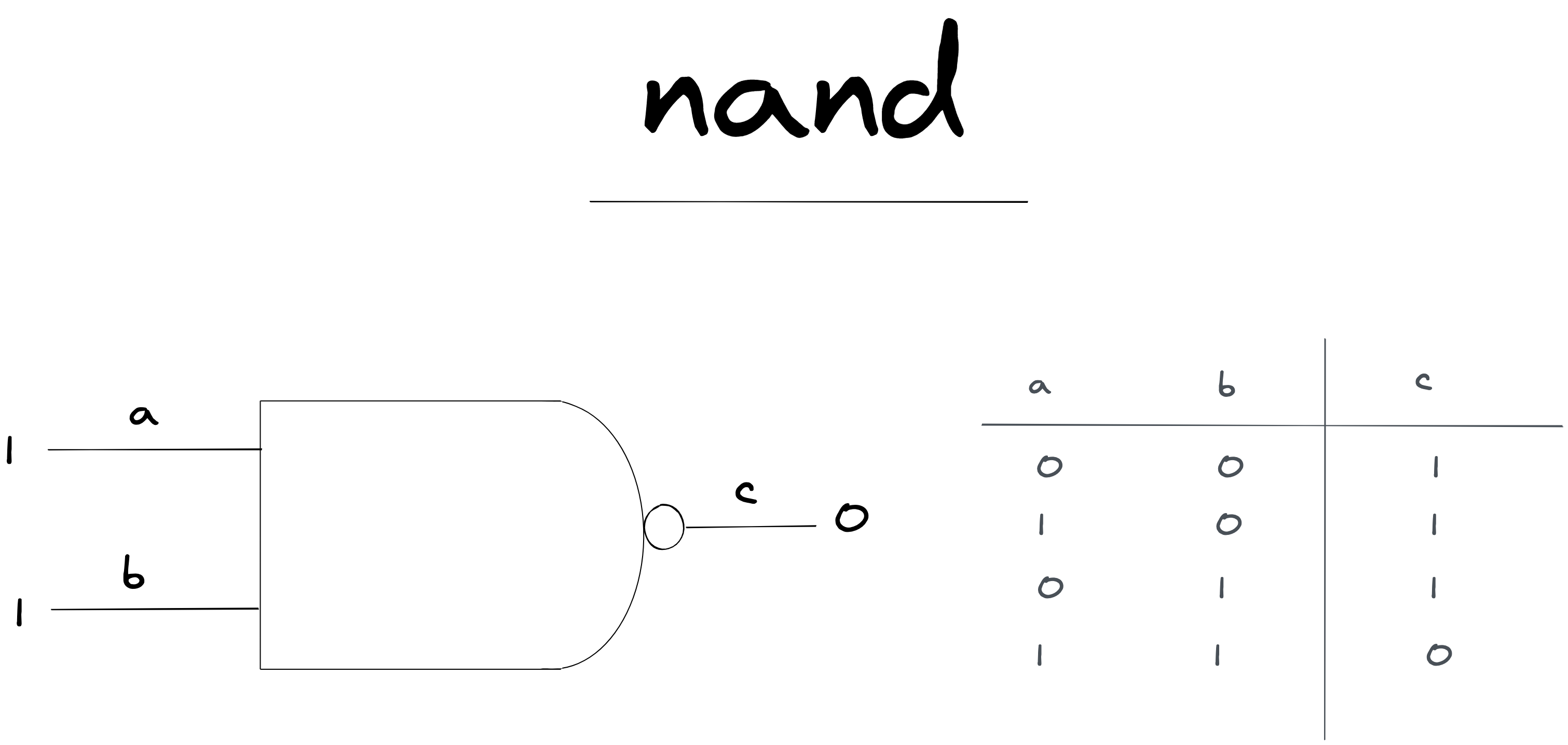
This describes a NAND gate. A NAND gate is a machine that has two input wires. If both input wires have a “high” charge (represented as 1), the output charge is “low” (represented as zero). With any other combination of input charges, the output charge is high.
Notice that the wires carry a charge, but we choose to interpret meaning in the charge. “high charge” means 1, and “low charge” means 0. Nothing changes in the machine, this is just something we decided as humans (1).
On the left you see a circuit diagram. You can read it as input wires a and b carrying charges into the NAND gate. The NAND gate has a wire c, carrying the output charge. For all the circuit diagrams we’ll draw, you can read them as electricity “flowing” from left to right, or top to bottom.
On the right is a “truth” table for a NAND gate. This is just a fancy name for summarizing every state a NAND gate can be, based on the input wires.
Now, we can start even lower than a NAND gate, but this machine is simple enough. It can’t be so hard to build something that turns off when two inputs are turned on. You don’t have to take my word for it though, you can search up “building a NAND gate with transistors”, and come back when you’re convinced.
Time to code! 🙂
0: State
First things first, we need some way to represent the state of our circuit. We know that our RAM will be built completely from NAND gates, so let’s take inspiration from one:
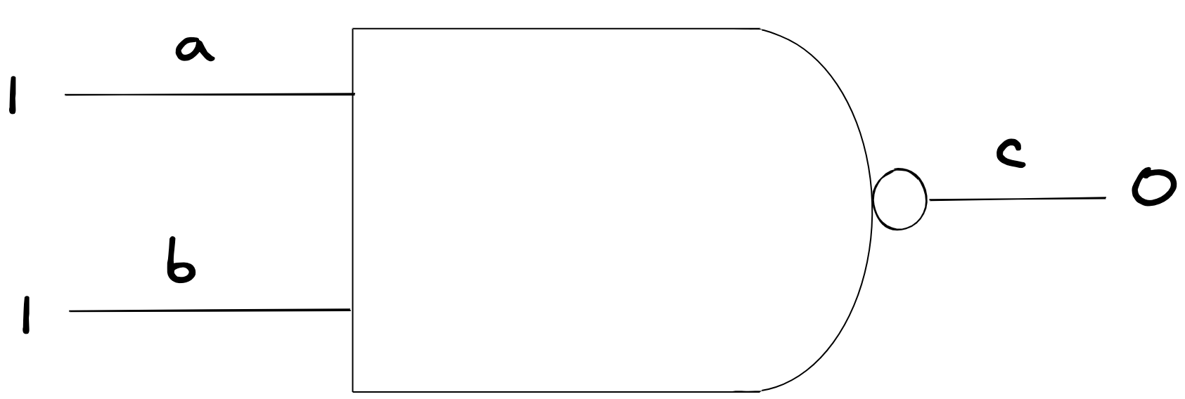
If we look at this example we can see that:
- We have wires.
- Wires have charges.
- We hook wires together with NAND Gates
Here’s one way we can map that to a data structure in Clojure:
(def ex-state-v0 {:charge-map {:a 1 :b 1 :c 0}
                  :nand-gates [{:ins [:a :b]
                                :out :c}]})
We can use keywords to represent our wires. We can also keep a map that tells us the charges of our wires. Finally, we can keep a list of NAND gates, which tell us how these wires connect.
Fine enough way to represent our circuit for now! Let’s create a few functions that can help us manage this representation:
; update state v0
; ---------------

(def empty-state {:charge-map {} :nand-gates []})

(defn charge [state wire]
  (get-in state [:charge-map wire]))

(defn charges [state wires]
  (map (partial charge state) wires))

(defn set-charge [state wire charge]
  (assoc-in state [:charge-map wire] charge))

(defn wire-nand-gate [state a b o]
  (update state :nand-gates conj {:ins [a b] :out o}))
These are all the basic tools we need to “connect” a NAND gate into our circuit. Let’s try them out in the REPL:
(charges (-> empty-state
               (set-charge :a 1)
               (set-charge :b 0))
           [:a :b])
; => (1 0)
(wire-nand-gate empty-state :a :b :c)
; => {:charge-map {}, :nand-gates [{:ins [:a :b], :out :c}]}
Nice! We can now “wire” up a circuit. Let’s run some electricity through it.
1: Trigger
To figure out how to simulate electricity into our circuit, let’s remember our diagram again:
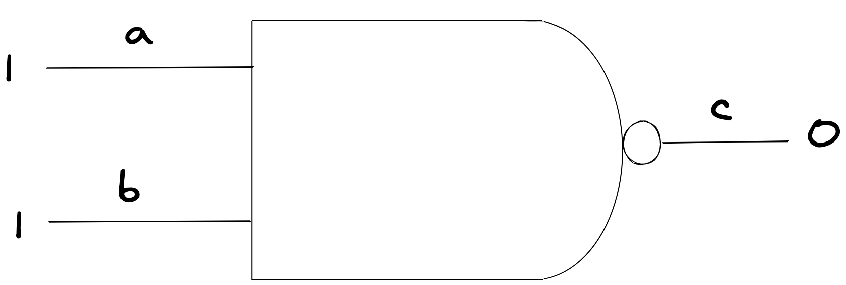
One way we can model this is to imagine that electricity is like water: It “flows” from sources into wires, and “triggers” all the devices that are connected to those wires.
With a model like that, here’s what would happen if a charge was “triggered” on a:
- First,
a‘s charge would update. - After that
a‘s charge would transfer to all the NAND gates that are connected to it. In this case, it would be our one NAND gate above. - Each NAND gate would then recompute its charge, and if it changed, trigger its output wire in turn. In our case that’s
c - If
cwas connected to otherNANDgates, those gates would trigger, and the process would continue.
Now, this is a very naive view of how electricity works (2), but it’s good enough for us to model RAM!
Let’s translate this into code.
To do that, we need a way to model what a NAND gate does:
(defn nand-output [a b]
(if (= a b 1) 0 1))(nand-output 0 0)
; => 1
(nand-output 1 1)
; => 0Our nand-output function takes two input charges, and produces the output charge that a NAND gate would produce.
Next, we need a function to find all the NAND gates that are connected to a specific wire:
(defn dependent-nand-gates [state wire]
  (filter
    (fn [{:keys [ins]}] (some #{wire} ins))
(:nand-gates state)))(dependent-nand-gates (wire-nand-gate empty-state :a :b :c) :a)
; => ({:ins [:a :b], :out :c})This searches all of our NAND gates in our circuit, and finds the ones which are connected to a specific wire.
With that, we have what we need to implement trigger:
(declare trigger-nand-gate)
(defn trigger
  ([state wire new-v]
   (let [old-charge (charge state wire)
         state' (set-charge state wire new-v)
         new-charge (charge state' wire)]
     (if (= old-charge new-charge)
       state'
       (reduce (fn [acc-state out] (trigger-nand-gate acc-state out))
               state'
               (dependent-nand-gates state' wire))))))
This follows exactly the model we described:
- Update the charge of the wire that was triggered
- Find all the
NANDgates that the wire was connected too - Trigger those
NANDgates if needed.
What’s left is to implement what a NAND gate does when it is triggered:
(defn trigger-nand-gate
  [state {:keys [ins out]}]
  (let [new-charge (apply nand-output (charges state ins))]
    (trigger state out new-charge)))
This calculates the new charge of a NAND gate, and triggers the output wire with that charge.
Great, we have a way to simulate charges flowing through NAND gates!
One final helper function: let’s create something that will will let us “trigger” many wires:
(defn trigger-many [state wires charges]
  (reduce
    (fn [acc-state [wire charge]]
      (trigger acc-state wire charge))
    state
    (map vector wires charges)))
We’ll want to do this so much that it’s good to have around.
2: Simulate NAND
We have what we need to simulate a simple charge flowing through a NAND gate. Let’s write a test for that:
(deftest test-nand-gate
  (let [s1 (-> empty-state
               (wire-nand-gate :a :b :o)
               (trigger-many [:a :b] [1 0]))
        s2 (-> s1
               (trigger :b 1))]
    (testing "just a is on"
      (is (= '(1 0 1) (charges s1 [:a :b :o]))))
    (testing "both a and b are on"
      (is (= '(1 1 0) (charges s2 [:a :b :o]))))))
; Ran 1 test containing 2 assertions.
; No failures.Works like a charm!
3: Simulate NOT
What would happen, if we took a NAND gate, and fed the same wire in both inputs?
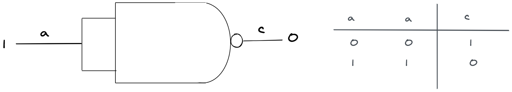
Well, the output would end up being the opposite of its input. When a is zero, c is 1, when a is 1, c is 0. Boom, that happens to be a NOT gate. Here’s how that looks:
To implement our NOT gate, we can do exactly as our diagram described: Feed the same wire to both inputs of a NAND gate:
(defn wire-not-gate
  ([state a o]
   (wire-nand-gate state a a o)))
🤯 1 line of code. If we test that out…
(deftest test-not-gate
  (let [s1 (-> empty-state
               (wire-not-gate :a :o)
               (trigger :a 0))
        s2 (-> s1
               (trigger :a 1))]
    (testing "a is off"
      (is (= '(0 1) (charges s1 [:a :o]))))
    (testing "a is on"
      (is (= '(1 0) (charges s2 [:a :o]))))))
; Ran 1 test containing 2 assertions.
; No failuresIt works! Onwards.
4: Simulate AND
What if we plugged the output of one NAND as the input of a NOT gate?
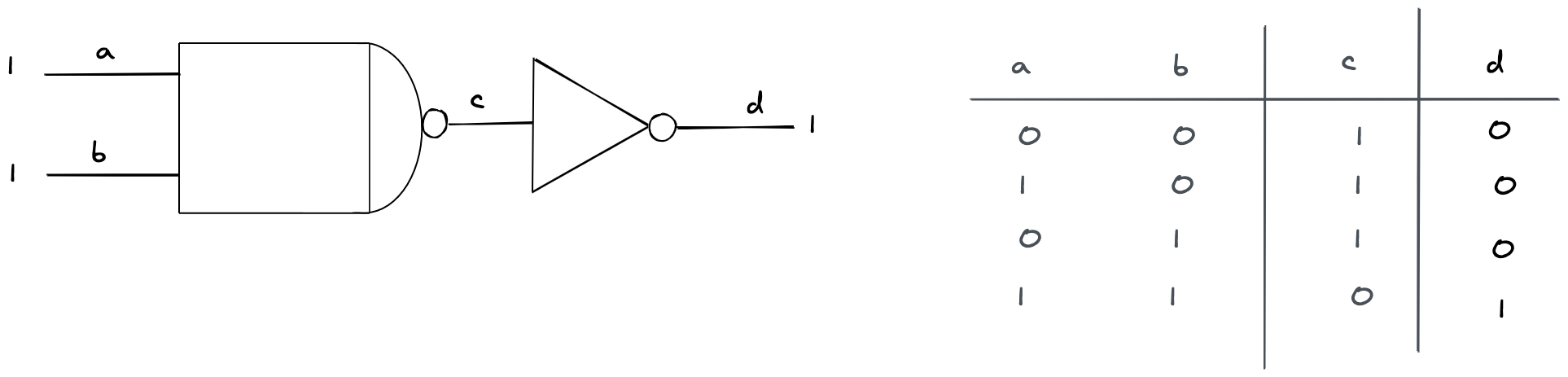
Well, it would be opposite of a NAND gate: d would only be 1 when both a and b are 1. That’s the AND gate:
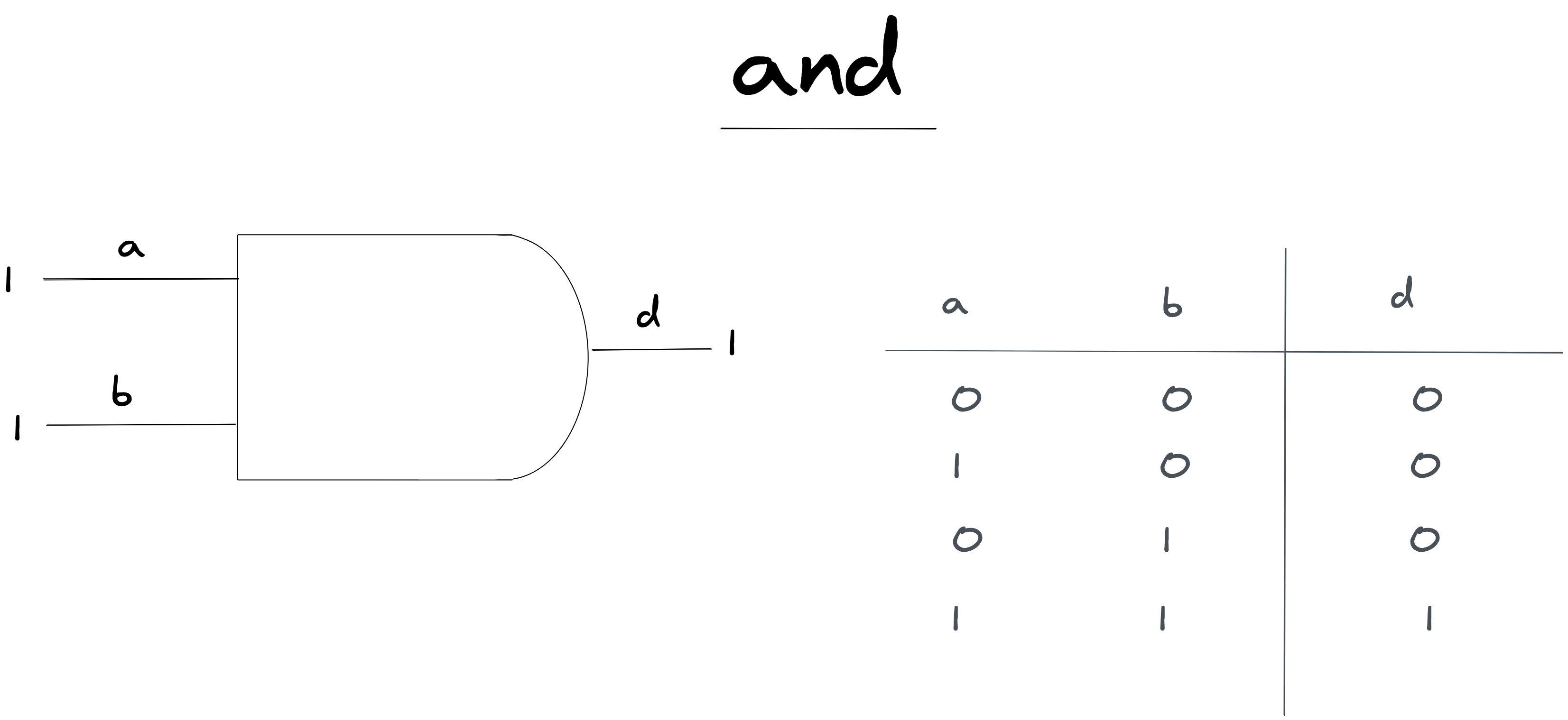
To implement AND, we can follow just that schematic:
(defn wire-and-gate [state a b o]
  (let [nand-o :c]
    (-> state
        (wire-nand-gate a b nand-o)
        (wire-not-gate nand-o o))))
This would work…almost. The tricky thing here is that inside the function we have an “intermediary” wire c, which connects the NAND gate and NOT gate. If we made two AND gates for example, then they would share the same wire :c!
To fix this, let’s write some helper functions to create unique wires:
(def _u (atom {}))
(defn uniq-n [k]
  (swap! _u update k (fn [i] (inc (or i 0))))
  (get @_u k))

(defn kw [& args]
  (->> args
       (map (fn [x] (if ((some-fn keyword? symbol?) x)
                      (name x)
                      x)))
       (apply str)
       keyword))

(defn wire
  ([n]
   (let [i (uniq-n n)]
     (if (> i 1) (kw n "#" i) n))))
Let’s see how it looks:
[(wire :a) (wire :a)]
=> [:a :a#2]
Now if we create a wire with a name that already exists, it’ll add a nice little “#2” beside it.
Nice! Let’s use it in wire-and-gate
(defn wire-and-gate [state a b o]
  (let [nand-o (wire (kw a b :and-nand-o))]
    (-> state
        (wire-nand-gate a b nand-o)
        (wire-not-gate nand-o o))))
If we test this out…
(deftest test-and-gate
  (let [s1 (-> empty-state
               (wire-and-gate :a :b :o)
               (trigger-many [:a :b] [1 0]))
        s2 (-> s1
               (trigger :b 1))]
    (testing "just a is on"
      (is (= '(1 0 0) (charges s1 [:a :b :o]))))
    (testing "a and b on"
      (is (= '(1 1 1) (charges s2 [:a :b :o]))))))
; Ran 1 test containing 2 assertions.
; No failures.Works like a charm!
5: Simulate Bits
Now comes one of the hardest and most important circuits we’ll need to understand. Let’s start by describing our goal:
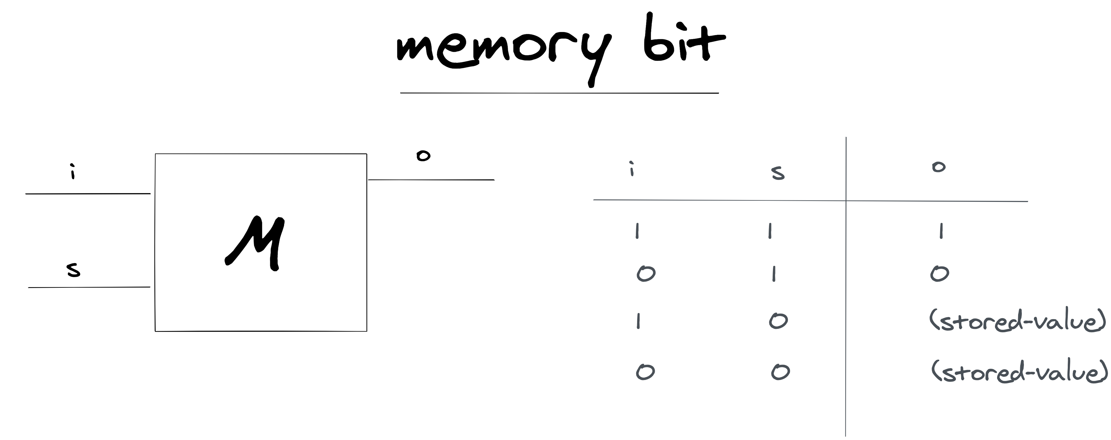
Notice the interesting thing here. When the s wire is “1”, the value of i is transferred to o. When it is “0”, the value of o is no longer affected by i. o's charge is whatever it was before.
If we can make something like this, that would mean that the charge on “o” is stored. Since it can be either 1 or 0, we can in effect “store” 1 bit of data.
Here’s how we can do this:
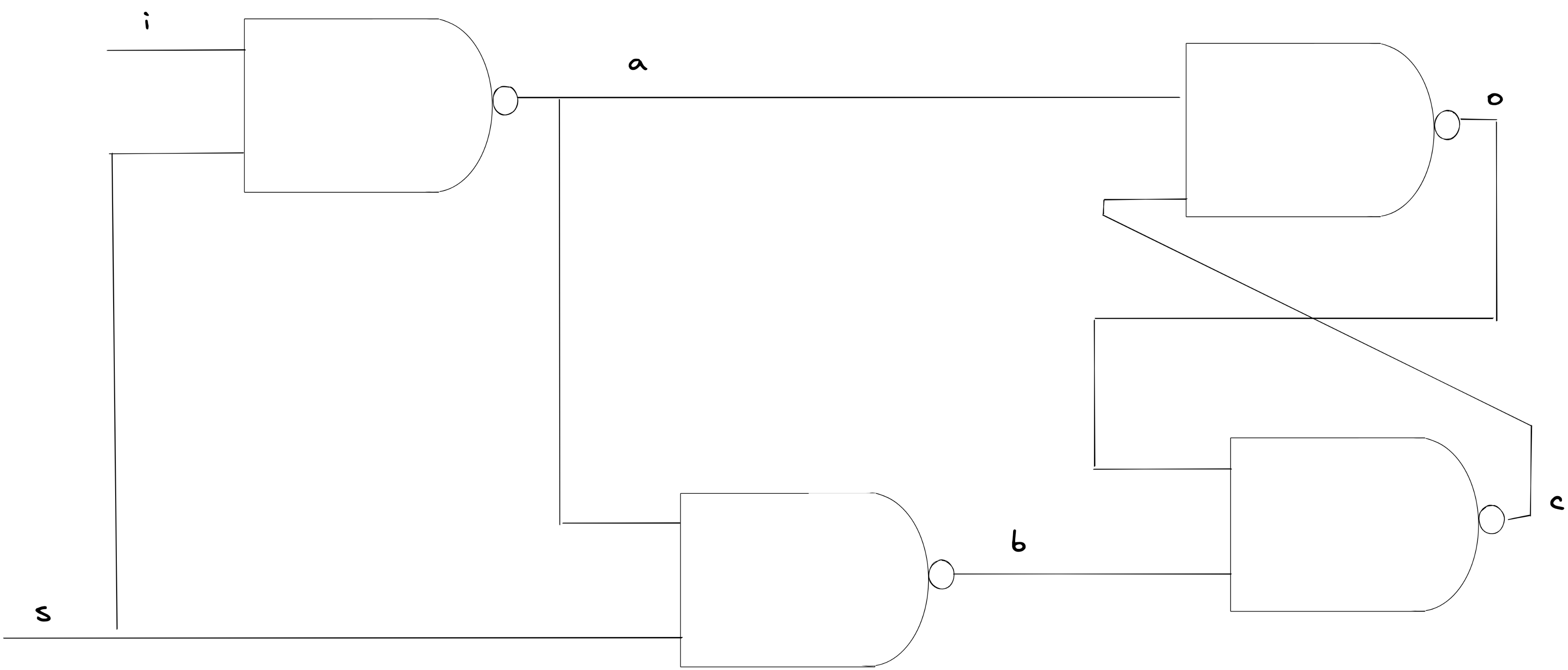
The trick with this circuit is the way o and c are connected together. This intertwining thing is called a “latch”, because once a charge gets set in a certain way, these gates will find an equilibrium that causes o to be stored. Pretty cool!
This circuit is pretty complicated and a bit hard to understand (3), but we’ve got the power of simulation at our fingertips! Let’s try building it and test it out:
(defn wire-memory-bit
  "To understand the variables in this circuit,
  follow along with the diagram in the tutorial"
  ([state s i o]
   (let [a (wire :a)
         b (wire :b)
         c (wire :c)]
     (-> state
         (wire-nand-gate i s a)
         (wire-nand-gate a s b)
         (wire-nand-gate a c o)
         (wire-nand-gate b o c)))))
Looks so pretty for such a complicated machine. Now the ultimate question…will it work?!
(deftest test-memory-bit
  (let [s1 (-> empty-state
               (wire-memory-bit :s :i :o)
               (trigger-many [:i :s] [1 0]))
        s2 (-> s1
               (trigger :s 1))
        s3 (-> s2
               (trigger-many [:s :i] [0 0]))]
    (testing "turning i on does not affect the rest"
      (is (= '(0 1 0) (charges s1 [:s :i :o]))))
    (testing "enabling set transfers i to o"
      (is (= '(1 1 1)
             (charges s2 [:s :i :o]))))
    (testing "disabling set, removes further effects on o"
      (is (= '(0 0 1)
             (charges s3 [:s :i :o]))))))
; Ran 1 test containing 3 assertions.
; No failures.Oh ma gad…it works!
6: Simulate Bytes
Now that we have a bit, we can take one s wire and tie 8 memory bits together with it. That would let us set 8 bits together, which means we can “store” 8 bits of data…which gives us a byte! (5). Here’s how that would look:
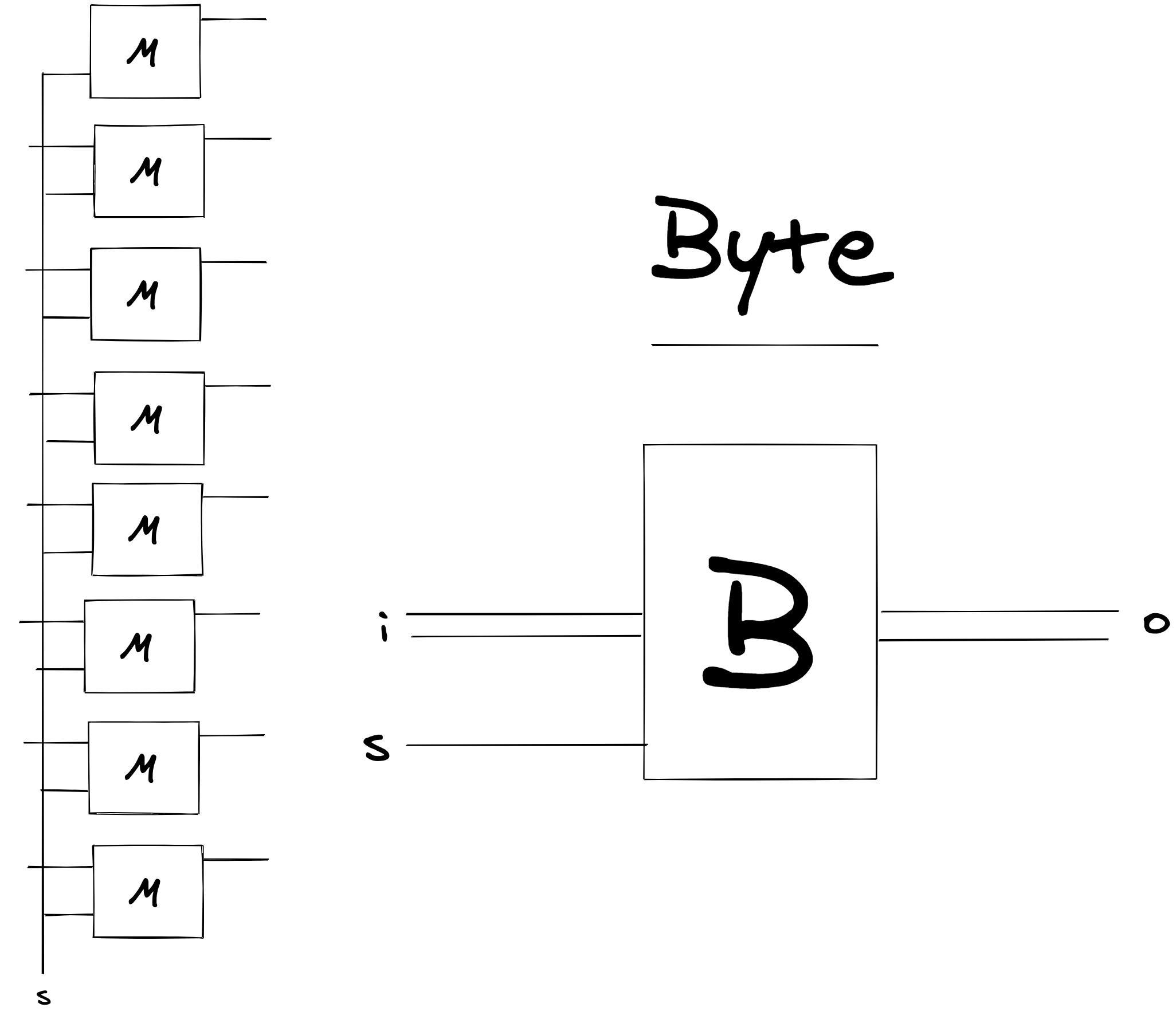
Note that in our diagram now “two wires together” is short-hand for writing 8 wires.
Let’s write up a byte in our simulation:
(defn wire-byte [state s ins outs]
  (reduce (fn [acc-state [i o]]
            (wire-memory-bit acc-state s i o))
          state
          (map vector ins outs)))
Easy peasy!
To test this out though, we’re going to need a way to “create” a bunch of names for wires. Let’s write a few helper functions that make this easy:
(defn names [n r]
  (mapv (fn [i] (kw n "-" i)) (range r)))

(def wires (comp (partial mapv wire) names))
Here’s how we could make 8 wires with the name :i
(wires :i 8)
; => [:i-0 :i-1 :i-2 :i-3 :i-4 :i-5 :i-6 :i-7]
Nice! Now to write our test for the byte:
(deftest test-byte
  (let [ii (wires :i 8)
        os (wires :o 8)
        s1 (-> empty-state
               (wire-byte :s ii os)
               (trigger-many ii [1 1 1 0 0 0 0 0])
               (trigger :s 0))
        s2 (-> s1
               (trigger :s 1))
        s3 (-> s2
               (trigger :s 0)
               (trigger-many ii [0 0 0 0 0 0 0 1]))]
    (testing "disabling set, removes further effects on o"
      (is (= '(1 1 1 0 0 0 0 0)
             (charges s1 ii)))
      (is (= '(0 0 0 0 0 0 0 0)
             (charges s1 os))))
    (testing "set s, so os become 1 1 1"
      (is (= '(1 1 1 0 0 0 0 0)
             (charges s2 ii)))
      (is (= '(1 1 1 0 0 0 0 0)
             (charges s2 os))))
    (testing "freeze by disabling s. see that further changes to i do nothing to o"
      (is (= '(0 0 0 0 0 0 0 1)
             (charges s3 ii)))
      (is (= '(1 1 1 0 0 0 0 0)
             (charges s2 os))))))
Phoof…does it work?
; Ran 1 test containing 6 assertions.
; No failures.
Yes!
7: Simulate Enabler
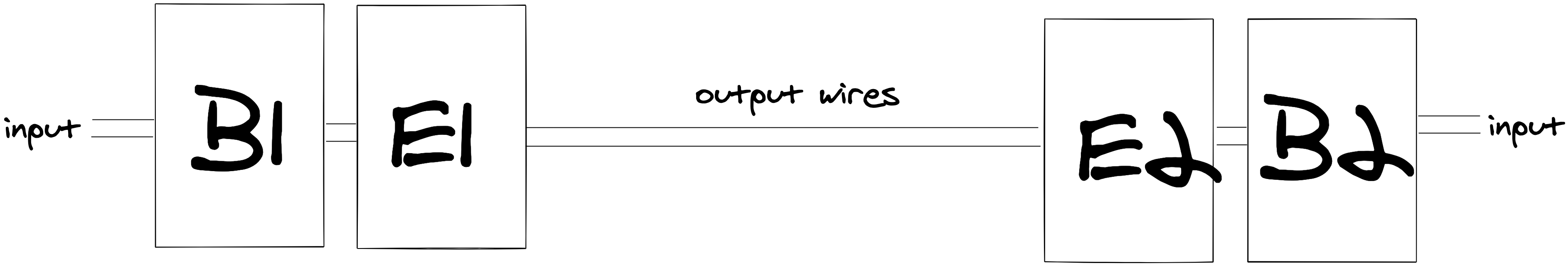
Now, imagine we had two bytes, connected like this:
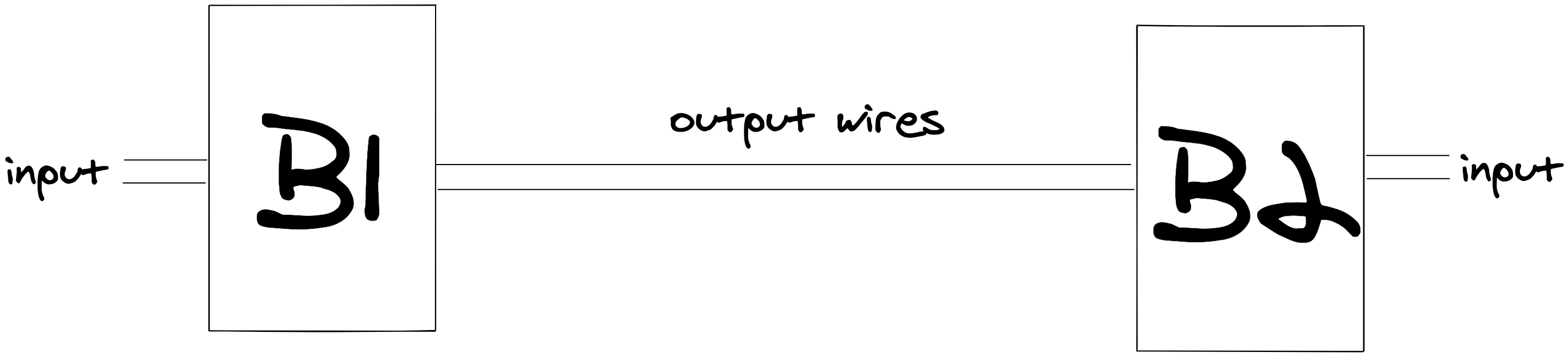
Notice how the output wires are shared between B1 and B2. If B1 had a charge of “11110000”, and B2 had a charge of “0001111”, what would happen to the output wires? It would carry a charge of “1111111”! Say we wanted to make sure only one of the bytes sent their output charge into output wires. How could we do that?
We’ll need a new machine. Let’s consider what would happen if we took a bunch of AND gates, and connected them together like this:
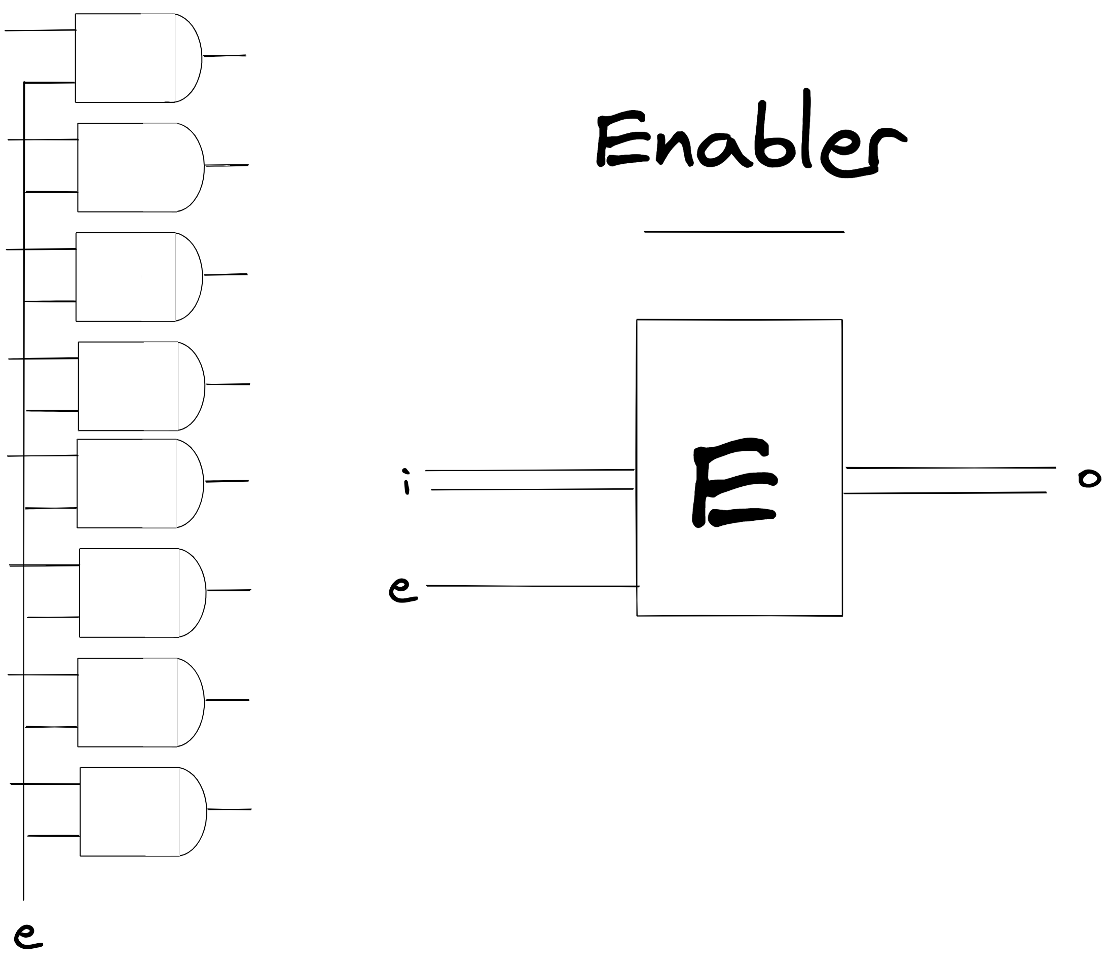
Now, if the “e” wire is “on”, the output wires are charged with whatever the input wires are. Buut, if the “e” wire is “off”, the output zeroes out. This machine is called the “enabler”. If we put this together right, we could control what charge gets sent to output wires!
Let’s set it up first, it should be easy peasy:
(defn wire-enabler
  [state e ins outs]
  (reduce
    (fn [acc-state [in out]]
      (wire-and-gate acc-state e in out))
    state
    (map vector ins outs)))
Looks nice! Let’s see the test:
(deftest test-enabler
  (let [ii (wires :i 8)
        os (wires :o 8)
        s1 (-> empty-state
               (wire-enabler :e ii os)
               (trigger-many ii [1 1 1 0 0 0 0 0])
               (trigger :e 0))
        s2 (trigger s1 :e 1)
        s3 (trigger s2 :e 0)]
    (testing "is should be set, but os should be 0"
      (is (= '(1 1 1 0 0 0 0 0)
             (charges s1 ii)))
      (is (= '(0 0 0 0 0 0 0 0)
             (charges s1 os))))
    (testing "os should pass if enabled"
      (is (= '(1 1 1 0 0 0 0 0)
             (charges s2 ii)))
      (is (= '(1 1 1 0 0 0 0 0)
             (charges s2 os))))
    (testing "os should revert if disabled"
      (is (= '(1 1 1 0 0 0 0 0)
             (charges s3 ii)))
      (is (= '(0 0 0 0 0 0 0 0)
             (charges s3 os))))))
; Ran 1 test containing 6 assertions.
; No failures.🔥
8: Simulate Register
Here’s how we could “fix” our problem with B1 and B2:
If we stuck an “enabler” in front of each byte, we could control what gets sent to output wires. If we wanted to have B1's charge, we would “enable E1”, and make sure E2 was disabled, and vice versa.
This combination of byte and enabler is so common that we can build a machine for that:
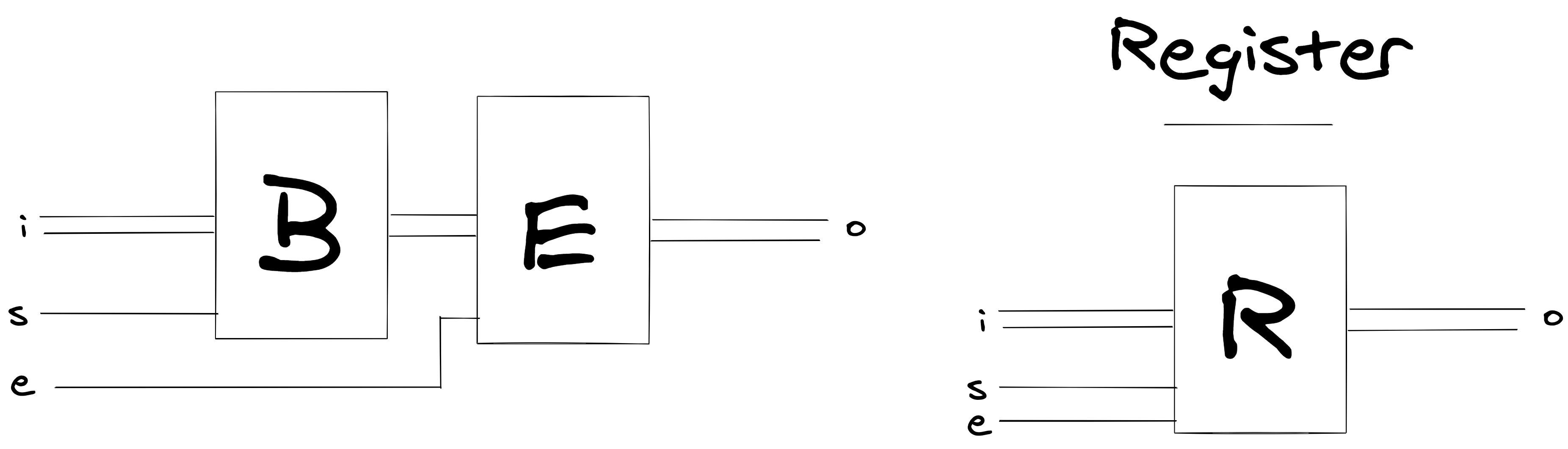
It’s called a register! Registers let us both control what bytes are stored, and when these bytes are exposed as output.
To set this up, all we need to do is to tie together a byte and an enabler:
(defn wire-register [state s e ins bits outs]
  (-> state
      (wire-byte s ins bits)
      (wire-enabler e bits outs)))
Badabing, badaboom, it should work. This is a pretty important machine, so let’s make darn sure it works:
(deftest test-register
  (let [ii (wires :i 8)
        bs (wires :b 8)
        os (wires :o 8)
        s1 (-> empty-state
               (wire-register :s :e ii bs os)
               (trigger-many ii [1 1 1 0 0 0 0 0])
               (trigger :s 0)
               (trigger :e 0))
        s2 (trigger s1 :s 1)
        s3 (trigger s2 :e 1)
        s4 (-> s3
               (trigger :s 0)
               (trigger-many ii [0 0 0 0 0 0 0 1]))
        s5 (trigger s4 :e 0)]
    (testing "is should be set, but bs and os should be 0, b/c s & e are 0"
      (is (= '(1 1 1 0 0 0 0 0)
             (charges s1 ii)))
      (is (= '(0 0 0 0 0 0 0 0)
             (charges s1 bs)))
      (is (= '(0 0 0 0 0 0 0 0)
             (charges s1 os))))
    (testing "is & bs should be set, as s is on. but os should be 0, b/c e is off"
      (is (= '(1 1 1 0 0 0 0 0)
             (charges s2 ii)))
      (is (= '(1 1 1 0 0 0 0 0)
             (charges s2 bs)))
      (is (= '(0 0 0 0 0 0 0 0)
             (charges s2 os))))
    (testing "is & bs should be set, as s is on. but os should be 0, b/c e is off"
      (is (= '(1 1 1 0 0 0 0 0)
             (charges s3 ii)))
      (is (= '(1 1 1 0 0 0 0 0)
             (charges s3 bs)))
      (is (= '(1 1 1 0 0 0 0 0)
             (charges s3 os))))
    (testing "is should be new v, but bs and os should be the old value"
      (is (= '(0 0 0 0 0 0 0 1)
             (charges s4 ii)))
      (is (= '(1 1 1 0 0 0 0 0)
             (charges s4 bs)))
      (is (= '(1 1 1 0 0 0 0 0)
             (charges s4 os))))
    (testing "os should 0 out again"
      (is (= '(0 0 0 0 0 0 0 1)
             (charges s5 ii)))
      (is (= '(1 1 1 0 0 0 0 0)
             (charges s5 bs)))
      (is (= '(0 0 0 0 0 0 0 0)
             (charges s5 os))))))
; Ran 1 test containing 15 assertions.
; No failures.Very cool!
9: Simulate Bus
Okay, let’s continue our experiment, to an astounding result: what if we connected the inputs and outputs of a bunch of registers to the same wires?
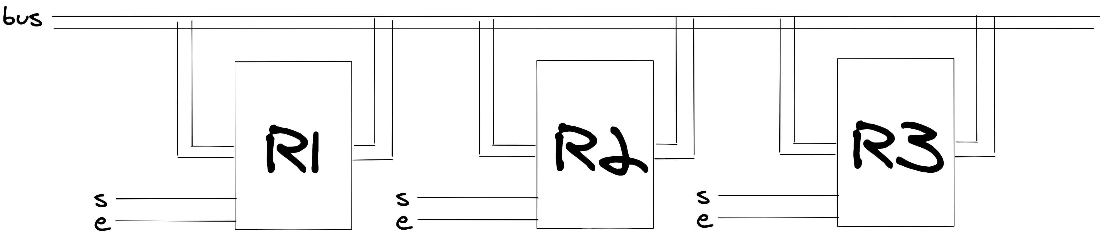
Now, remember that s allows us to decide what gets “stored” into a register, and “e” lets us “pass” the charge of a register’s byte through to the output.
What would happen in the following scenario. Say R1’s byte contains “111”, all s and e wires are 0.
- “Charge
R1’seto 1”.- Now
R1would enable, and thebuswires would carry the same charge asR1
- Now
- “Charge
R3’ssto 1, then 0”.- This would set the value of
R3, to the current charge flowing inbus. This happens to be the output ofR1!
- This would set the value of
- “Set
R1'seto 0” Now the current inbuswould disappear again
The result? The byte in R1 would have been “copied” to R3. We’ve just created a bus.
To create a bus, all we need to do is to connect a register’s input and output to the same “bus” wires:
(defn wire-bus [state bus-wires s e bits]
  (wire-register state s e bus-wires bits bus-wires))
This is only a single line, but it’s pretty important to get right. It’s what lets us “copy” registers after all. Let’s see if it works:
(deftest test-wire-bus
  (let [bw (wires :bw 8)
        r1-bits (wires :r1 8)
        r2-bits (wires :r2 8)
        r3-bits (wires :r2 8)
        s1 (-> empty-state
               (wire-bus bw :s1 :e1 r1-bits)
               (wire-bus bw :s2 :e2 r2-bits)
               (wire-bus bw :s3 :e3 r3-bits)
               (trigger-many bw [1 1 1 0 0 0 0 0])
               (trigger :s1 0)
               (trigger :e1 0))
        s2 (-> s1
               (trigger :s1 1)
               (trigger :s1 0)
               (trigger-many bw [0 0 0 0 0 0 0 0]))
        s3 (-> s2
               (trigger :e1 1)
               (trigger :s3 1)
               (trigger :s3 0)
               (trigger :e1 0))]
    (testing "only bus should have charge"
      (is (= '(1 1 1 0 0 0 0 0)
             (charges s1 bw)))
      (is (= '(0 0 0 0 0 0 0 0)
             (charges s1 r1-bits)))
      (is (= '(0 0 0 0 0 0 0 0)
             (charges s1 r2-bits)))
      (is (= '(0 0 0 0 0 0 0 0)
             (charges s1 r3-bits))))
    (testing "r1 should have the charge"
      (is (= '(0 0 0 0 0 0 0 0)
             (charges s2 bw)))
      (is (= '(1 1 1 0 0 0 0 0)
             (charges s2 r1-bits)))
      (is (= '(0 0 0 0 0 0 0 0)
             (charges s2 r2-bits)))
      (is (= '(0 0 0 0 0 0 0 0)
             (charges s2 r3-bits))))
    (testing "move r1 to r3"
      (is (= '(0 0 0 0 0 0 0 0)
             (charges s3 bw)))
      (is (= '(1 1 1 0 0 0 0 0)
             (charges s3 r1-bits)))
      (is (= '(0 0 0 0 0 0 0 0)
             (charges s2 r2-bits)))
      (is (= '(1 1 1 0 0 0 0 0)
             (charges s3 r3-bits))))))
; Ran 1 test containing 12 assertions.
; 4 failures, 0 errors.🙀 uh oh, it doesn’t work…
10: Evolve Trigger
Let’s look at this diagram again:

Remember that the bus wires can “receive” a charge now from the outputs of R1 , R2, or R3. Here’s how our set-charge looked:
(defn set-charge [state wire charge]
  (assoc-in state [:charge-map wire] charge))
Imagine if R1 was enabled and a wire was charged to 1. What would happen if R3 got triggered?
It would overwrite our charge!
Time to to evolve our model. One way to think about it, is that bus wires now have multiple “sources” that can provide a charge. Let’s update our charge functions to keep track of this “source”
(defn set-charge
  ([source state w v]
   (assoc-in state [:charge-map w source] v)))

(defn charge [{:keys [charge-map]} w]
  (when-let [charges (vals (charge-map w))]
    (apply max charges)))


(set-charge empty-state :nand-a :w 1)
; => {:charge-map {:w {:nand-a 1}}, :nand-gates []}
(let [s1 (-> empty-state
               (set-charge :nand-a :w 1)
               (set-charge :nand-b :w 0))]
    (charge s1 :w))
; => 1
Nice. Now, whenever we set a charge, we are aware of waht source it comes from.
Let’s update trigger to include a source too:
(defn trigger
  ([state wire new-v] (trigger :repl state wire new-v))
  ([source state wire new-v]
   (let [old-charge (charge state wire)
         state' (set-charge state source wire new-v)
         new-charge (charge state' wire)]
     (if (= old-charge new-charge)
       state'
       (reduce (fn [acc-state out] (trigger-nand-gate acc-state out))
               state'
               (dependent-nand-gates state' wire))))))
And let’s make trigger-nand-gate use a source:
(defn trigger-nand-gate
  [state {:keys [ins out]}]
  (let [new-charge (apply nand-output (charges state ins))]
    (trigger (apply kw (conj ins out)) state out new-charge)))
Now each NAND gate triggers with a specific name as a source. This would make it so R1's output trigger wouldn’t interfere with R2 output trigger! Let’s test out the bus again:
; Ran 1 test containing 12 assertions.
; No failures.
We’re back.
11: Simulate and-n
Right now, our and gate only tests whether two inputs are both 1. What if we wanted to test that three inputs are all 1? We could just wire up a bunch of AND gates together:
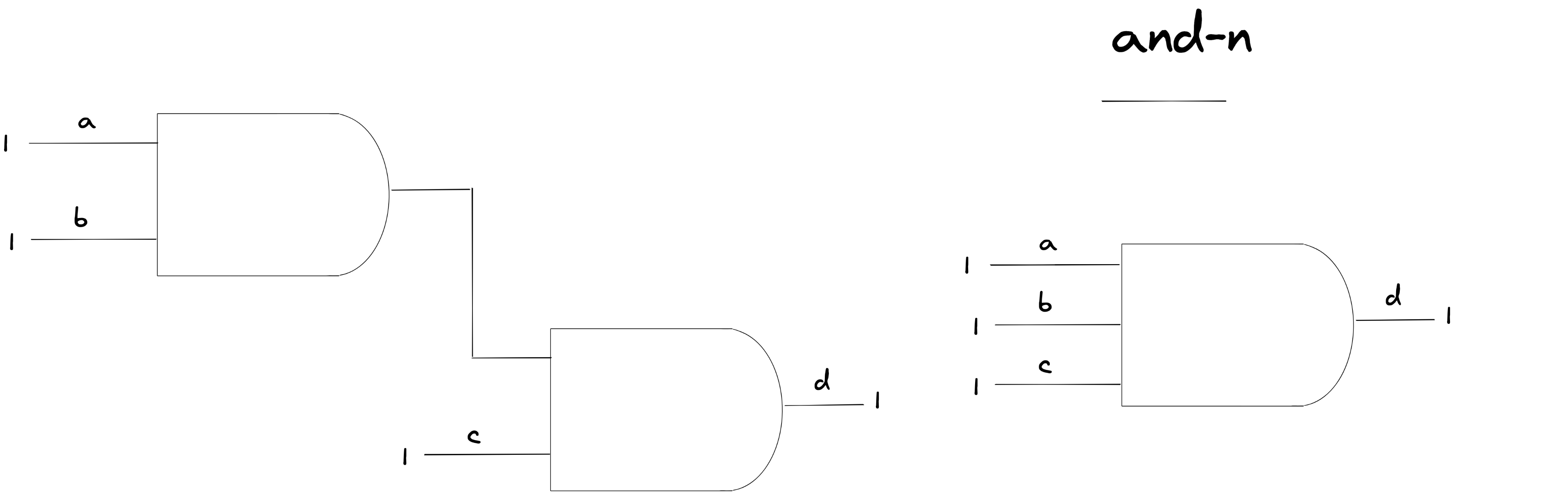
Let’s call this the AND-N gate. It can take N number of inputs, and produces one output. We can wire this up using some nice recursion:
(defn wire-and-n [state ins out]
  (let [[a b] (take 2 ins)
        rem (drop 2 ins)]
    (if-not (seq rem)
      (wire-and-gate state a b out)
      (let [w (wire (kw a b :-and))]
        (wire-and-n
          (wire-and-gate state a b w)
          (list* w rem)
          out)))))
We keep recursing wire up the inputs as AND gates, until we’re only left with two. Let’s see how it works:
(deftest test-and-n
  (let [ii [:a :b :c :d :e]
        s1 (-> empty-state
               (wire-and-n ii :o)
               (trigger-many ii [1 1 1 1 0]))
        s2 (trigger-many s1 ii [1 1 1 1 1])]
    (testing "if only some are charged, o is off"
      (is (= '(1 1 1 1 0)
             (charges s1 ii)))
      (is (= 0 (charge s1 :o))))
    (testing "if all are on, we are on"
      (is (= '(1 1 1 1 1)
             (charges s2 ii)))
      (is (= 1 (charge s2 :o))))))
; Ran 1 test containing 4 assertions.
; No failures.12: Simulate decoder
Now, Say we have two inputs (a b), and we want to know how they are charged: (a0 b0) (a0 b1) (a1 b0) (a1 b1).
We could make a machine that figures that out:
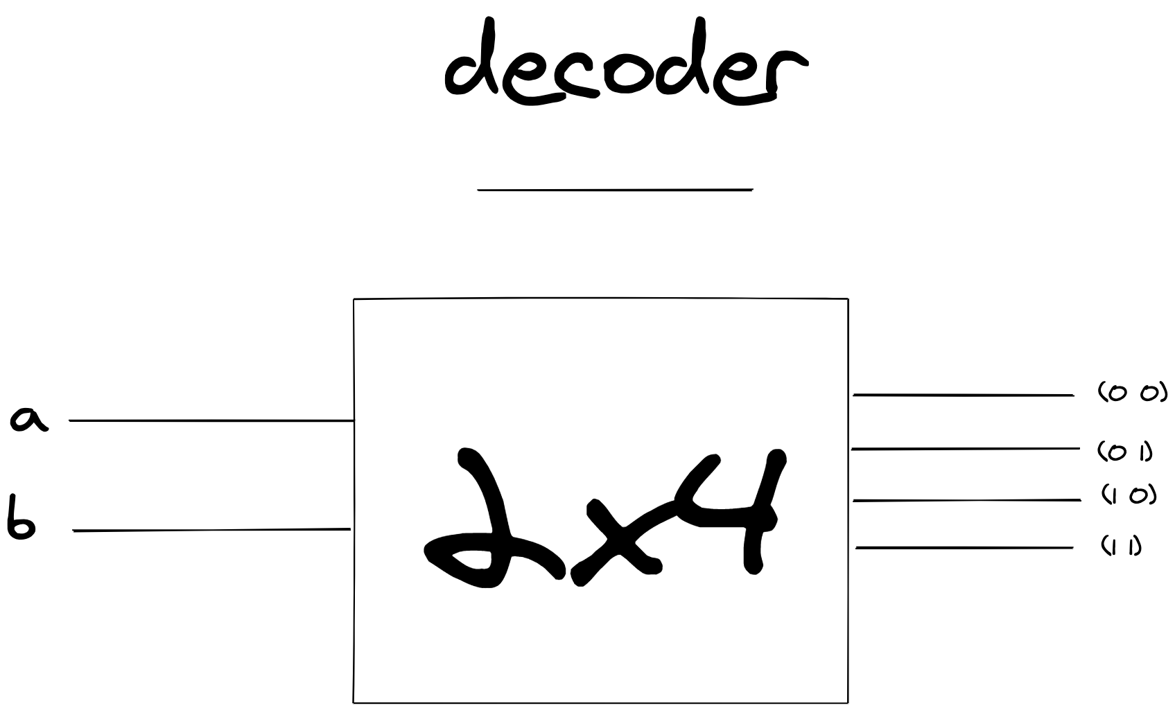
It’s called a decoder. It guarantees that only one wire will turn on, and each wire will represent a specific state of a and b. Here’s how we could do it:
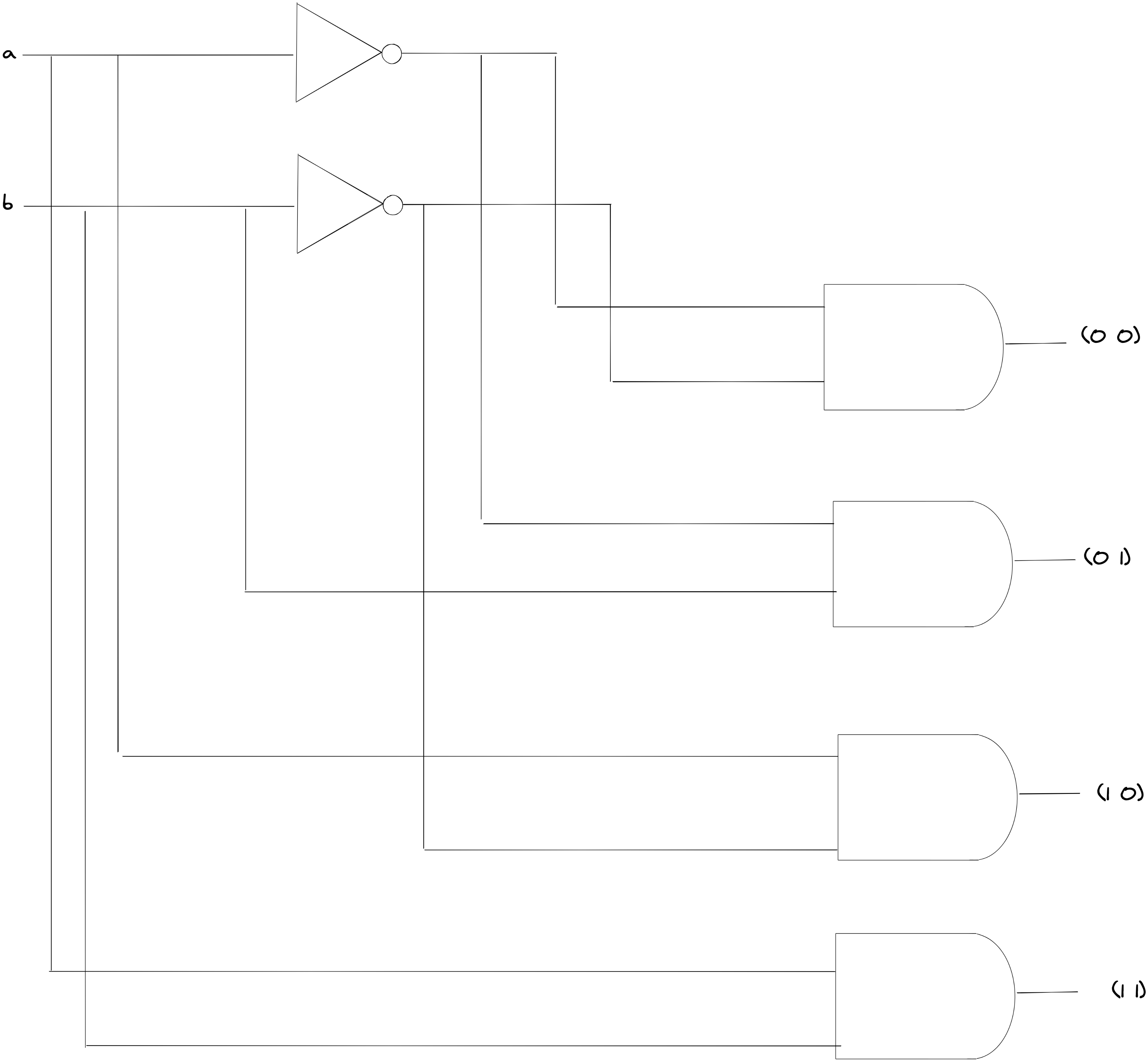
This looks like a lot, but in essence it’s pretty simple. Each input is wired into a NOT gate. Now let’s take an example: what would happen If we wire the NOT outputs of a & b to an AND gate?
If that AND output turned “1”, it would mean that both a and b had to be 0! This would mean the output wire of that AND gate, when “1”, represents the selection (a0 b0). We can keep wiring AND gates like this, to represent all different selections.
It can even be generalized: for N inputs, we create N NOT outputs. Then we can wire them up to and-n gates in such a way that the output represents the a special selection.
Let’s do that. First, we’ll need to install Clojure’s math combinatorics library in our deps.edn:
{:deps {org.clojure/math.combinatorics {:mvn/version "0.1.6"}}}Now let’s require it:
(:require [clojure.math.combinatorics :as c])With this we can create a quick function that produces our “wire” selection mapping:
(def decoder-mapping (partial c/selections [0 1]))(decoder-mapping 2)
; => ((0 0) (0 1) (1 0) (1 1))Perfect, this gives us a “selection”. We can use these “selections”, to decide what the combination of wires should be for an and-n gate.
Here’s how the decoder could look:
(defn wire-decoder
  [state ins outs]
  (let [ins-nots (mapv #(wire (kw % :-not)) ins)
        state' (reduce
                 (fn [acc-state [in out]]
                   (wire-not-gate acc-state in out))
                 state
                 (map vector ins ins-nots))
        state'' (reduce
                  (fn [acc-state [sel out]]
                    (let [and-ins (map-indexed
                                    (fn [i sign]
                                      (if (= sign 0)
                                        (nth ins-nots i)
                                        (nth ins i)))
                                    sel)]
                      (wire-and-n acc-state and-ins out)))
                  state'
                  (map vector (wire-mapping (count ins)) outs))]
    state''))
…Pretty elegant. Thank you Clojure. We first wire up a bunch of NOT wires. Then we generate a bunch of selections, and for each one wire up and and-n gate. We wire either from ins or in-nots, based on what the selection tells us.
The ultimate question…will it work?!
(deftest test-decoder
  (let [ii (wires :i 4)
        os (wires :o 16)
        sels (wire-mapping (count ii))
        sel (nth sels 5)
        o (nth os 5)
        s1 (-> empty-state
               (wire-decoder ii os)
               (trigger-many ii sel))]
    (testing "only 1 output is on"
      (is (= 1 (charge s1 o)))
      (is (every? zero? (charges s1 (remove #{o} os)))))))
; Ran 1 test containing 2 assertions.
; No failures.😦
13: Simulate Lookup
With all of this, we can wire together the first part of RAM. We need a way to “look up” a byte.
What if we took one byte — let’s call it mar — and wired the first 4 outputs to one decoder, and the last 4 outputs to another decoder?
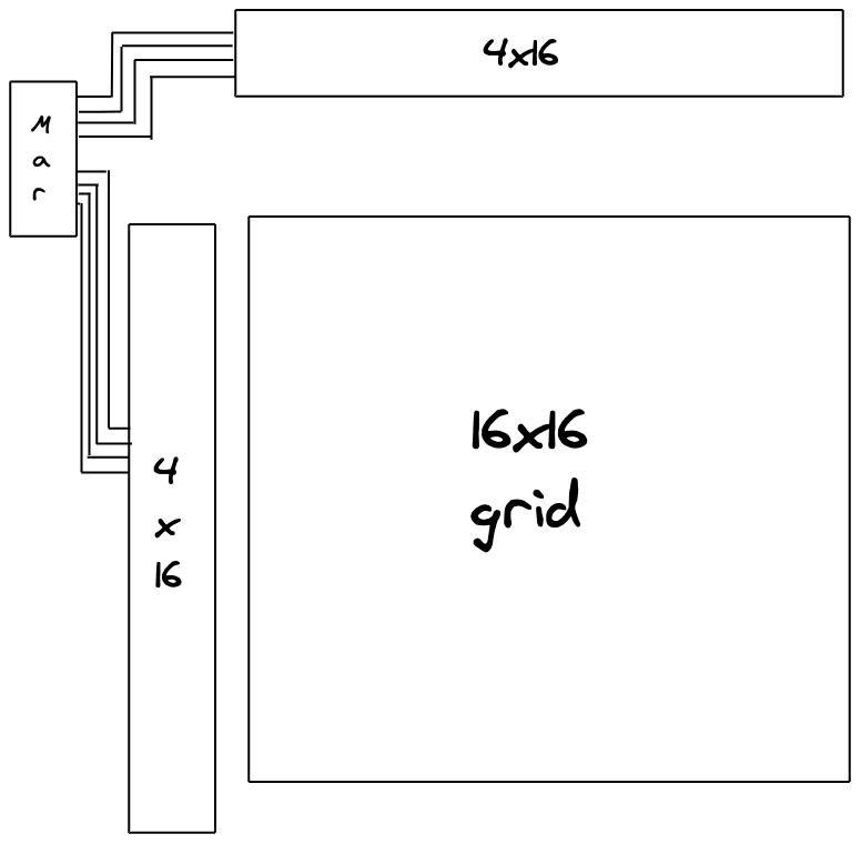
Well, this would produce 256 output wires. For each value in the mar byte, two output wires would be on: one from the first decoder, and the other from the second decoder.
We can think of this then, like a 16x16 grid. Each “byte” in mar represents a unique “intersection” in the grid. Now, in the future we can tie some registers to those grid wires, and when an “intersection” is on, we can make that register active! Pretty cool.
Let’s build it:
(defn wire-mar
  [state s is os first-4-outs last-4-outs]
  (-> state
      (wire-byte s is os)
      (wire-decoder (take 4 os) first-4-outs)
      (wire-decoder (drop 4 os) last-4-outs)))
Will it work?
(deftest test-mar
  (let [ii (wires :i 8)
        os (wires :o 8)
        first-4-decoders (wires :fd 16)
        last-4-decoders (wires :ld 16)
        s1 (-> empty-state
               (wire-mar :s ii os first-4-decoders last-4-decoders)
               (trigger-many ii [0 0 0 0 0 0 0 0])
               (trigger :s 0))
        sel (nth (wire-mapping 4) 5)
        s2 (trigger-many s1 ii (concat sel sel))
        s3 (-> s2
               (trigger :s 1)
               (trigger :s 0))
        test-idx (fn [state idx]
                   (let [fd (nth first-4-decoders idx)
                         ld (nth last-4-decoders idx)]
                     (is (= 1 (charge state fd)))
                     (is (every? zero? (charges state (remove #{fd} first-4-decoders))))
                     (is (= 1 (charge state ld)))
                     (is (every? zero? (charges state (remove #{ld} last-4-decoders))))))]
    (testing
      "by default only one wire is on, and it's the correct mapping"
      (test-idx s1 0))
    (testing
      "even if ii changes, sel doesn't change b/c s is 0"
      (test-idx s2 0))
    (testing
      "once s triggers, the sel does change"
      (test-idx s3 5))))
; Ran 1 test containing 12 assertions.
; No failures.Nice, we can look something up!
14: Simulate IO
Time to complete the picture:

We’re going to add an io bus at the bottom, a set wire an enable wire. For each “intersection” from our decoders, what would happen if we did this?
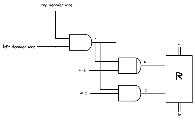
The top decoder wire and left decoder wire are fed into an AND gate that outputs x. x will only be “on” when both decoder wires are “on”. That means x would represent whether our intersection is active!
x and io-s are fed into an AND gate, which produces s. s will only turn on, when both io-s is charged and the intersection is active.
x and io-e are fed an AND gate, producing e. This will only turn on, when both io-e is charged, and the intersection is active.
After that, we take s e and the io wires, and connect them to a register.
If we follow that logic, it means that this register can be enabled and set, only when the intersection is “on”! If hooked this up to each intersection…all of a sudden we have 256 bytes of memory!
Let’s write this to work with just one intersection:
(defn wire-io
  [state io-s io-e ios decoder-o-1 decoder-o-2 register-bits]
  (let [x (wire (kw decoder-o-1 decoder-o-2 :x))
        s (wire (kw decoder-o-1 decoder-o-2 :s))
        e (wire (kw decoder-o-1 decoder-o-2 :e))]
    (-> state
        (wire-and-gate decoder-o-1 decoder-o-2 x)
        (wire-and-gate x io-s s)
        (wire-and-gate x io-e e)
        (wire-bus ios s e register-bits))))
Does it work?
(deftest test-io
  (let [ios (wires :io 8)
        rs (wires :r 8)
        s1 (-> empty-state
               (wire-io :s :e ios :w1 :w2 rs)
               (trigger-many ios [0 0 0 0 0 0 0 0])
               (trigger-many [:s :e :w1 :w2] [0 0 0 0])
               (trigger-many ios [1 1 1 0 0 0 0 0]))
        s2 (trigger s1 :s 1)
        s3 (trigger-many s2 [:w1 :w2] [1 1])
        s4 (-> s3
               (trigger :s 0)
               (trigger-many ios [0 0 0 0 0 0 0 0]))
        s5 (trigger s4 :e 1)]
    (testing "io set, but reg not affected"
      (is (= '(1 1 1 0 0 0 0 0) (charges s1 ios)))
      (is (= '(0 0 0 0 0 0 0 0) (charges s1 rs))))
    (testing "io set enable doesn't change, because intersection is not on"
      (is (= '(1 1 1 0 0 0 0 0) (charges s2 ios)))
      (is (= '(0 0 0 0 0 0 0 0) (charges s2 rs))))
    (testing "once intersection is on, charge transfers"
      (is (= '(1 1 1 0 0 0 0 0) (charges s3 ios)))
      (is (= '(1 1 1 0 0 0 0 0) (charges s3 rs))))
    (testing "once s turns off again, changes to io don't make a difference"
      (is (= '(0 0 0 0 0 0 0 0) (charges s4 ios)))
      (is (= '(1 1 1 0 0 0 0 0) (charges s4 rs))))
    (testing "if we turn on e, the r charge transfers to the io"
      (is (= '(1 1 1 0 0 0 0 0) (charges s5 ios)))
      (is (= '(1 1 1 0 0 0 0 0) (charges s5 rs))))))
; Ran 1 test containing 10 assertions.
; No failures.Great!
15: Wire RAM
Now, all we need to do is to wire-mar, and for each intersection, wire-io. Let’s do that:
(defn wire-ram [state mar-s mar-is io-s io-e ios]
  (let [mar-os (wires :mar-o 8)
        mar-first-4-outs (wires :mar-dec-f 16)
        mar-last-4-outs (wires :mar-dec-l 16)
        state' (wire-mar state mar-s mar-is mar-os mar-first-4-outs mar-last-4-outs)
        intersections (c/cartesian-product mar-first-4-outs mar-last-4-outs)
        state'' (reduce
                  (fn [acc-state [fw lw]]
                    (wire-io acc-state io-s io-e ios fw lw
                             (wires (kw fw lw :rb) 8)))
                  state'
                  intersections)]
    state''))
We first wire-mar. Then, we use cartesian-product to create a list of decoder intersections. For each of those intersections, we wire-io. Congratulations, you’ve wired together RAM!
16: Evolve state
Now, let’s take a look at how many NAND gates we have when we set our ram up:
(def ram (wire-ram
           empty-state
           :mar-s
           (wires :mar-i 8)
           :io-s
           :io-e
           (wires :io 8)))


(count (:nand-gates ram))
; => 14056
That’s a lot. Let’s try triggering something. How long does it take?
(trigger ram :mar-s 1)
; ...
Oi. Veery long. Why? Well, let’s remember our dependent-nand-gates:
(defn dependent-nand-gates [state wire]
  (filter
    (fn [{:keys [ins]}] (some #{wire} ins))
    (:nand-gates state)))
Every time a wire is triggered, we go through all 14056 NAND gates! That’s a lot of iteration for finding what is probably a few NAND gates.
Let’s make that faster:
(def empty-state {:charge-map {} :in->nand-gate {}})

(defn wire-nand-gate [state a b o]
  (reduce
    (fn [acc-state in]
      (update-in acc-state
                 [:in->nand-gate in]
                 (fn [xs] (conj (or xs []) {:ins [a b] :out o}))))
    state
    [a b]))

(defn dependent-nand-gates [state wire]
  (get-in state [:in->nand-gate wire]))
Here, we make accessing dependent NAND gates fast. Now it’s a matter of a dictionary lookup. If we try it out, it’ll be muuch faster!
17: Testing it out!
Okay, we built it, we made it fast, but will it work? Let’s imagine we built a machine like this:
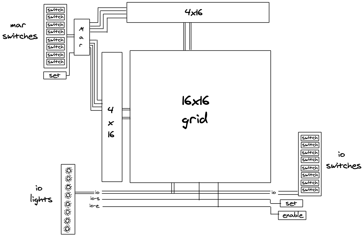
- We wire up
mar switchesto themarbyte, and add a switch to thesetwire- Depending on which switches we turn on, we can set a specific byte in
mar, and access a specific “register” in our grid!
- Depending on which switches we turn on, we can set a specific byte in
- We wire up
io lights- Whenever
iohas a charge, those lights will go on. Whichever light is on means 1, whichever light is off means 0. This will tell us the byte that is on theiobus!
- Whenever
- We tie the
io-swire to theio setswitch- When that switch is on, the
io-swire will be on, and as a result the currently active register’s “set” wire will be on. This will let us “save” whatever charge is inio!
- When that switch is on, the
- We tie the
io-ewire to anio enableswitch- When that switch is on, the
io-ewire will be on, and as a result the currently active register’s “enable” wire will be on. This will let us “pass” the active register’s charge intoio. That will causeio lightsto turn on and let us read the value in the register!
- When that switch is on, the
- We wire up
io switches- These switches will allow us to set a specific charge into
io. If we combine this by toggling our io “set” switch, we can save a specific charge into the active register!
- These switches will allow us to set a specific charge into
With a machine like that, we can now use our RAM! Here’s how.
(I recommend following along on the diagram above)
To access a specific register:
- Use the
MAR switches, to select the exact intersection we want, and toggle themar setswitch - Toggle the
io enableswitch . This will send the active register’s data intoio - Look at the
io lights: The combination of lights that are on represent the value of the register! - When done, toggle the
io enableswitch off.
To set data to a specific register:
- Use the
MAR switches, to select the exact intersection we want - Use the
IO switches, to set the charge in IO that represents the data we want to save. - Toggle the
io setswitch on. Now the charge ofiowill be saved to that specific register! - Now toggle the
io setswitch off, and toggle all theio switchesoff. - Badabing, badaboom. you’ve saved your data!
Let’s go ahead and create that machine.
First, let’s create a quick helper function to initialize our RAM:
(defn initialize-ram [mar-s mar-is io-s io-e ios]
  (-> empty-state
      (wire-ram mar-s mar-is io-s io-e ios)
      (trigger-many mar-is [0 0 0 0 0 0 0 0])
      (trigger-many ios [0 0 0 0 0 0 0 0])
      (trigger-many [mar-s io-s io-e]
                    [0 0 0])))
Next, here’s a quick helper function to “set” data into our mar byte:
(defn set-mar [state mar-s mar-is mar-vs]
  (-> state
      (trigger-many mar-is mar-vs)
      (trigger mar-s 1)
      (trigger mar-s 0)))
Here’s the function that follows our recipe to “access a specific register”
(defn handle-read [state mar-s mar-is io-e ios loc]
  (let [charge-bus-with-register (-> state
                                     (set-mar mar-s mar-is loc)
                                     (trigger io-e 1))
        next (-> charge-bus-with-register
                 (trigger io-e 0))]
    (println (str "> " (string/join (charges charge-bus-with-register
                                          ios))))
    next))
Here’s the function that follows our recipe to “set data to a specific register”
(defn handle-write [state mar-s mar-is io-s ios loc vs]
  (let [next (-> state
                 (set-mar mar-s mar-is loc)
                 (trigger-many ios vs)
                 (trigger io-s 1)
                 (trigger io-s 0)
                 (trigger-many ios [0 0 0 0 0 0 0 0]))]
    (println "> done")
    next))
With these two things, we can create a REPL loop:
(defn ram-repl []
  (println
    (str "🔥 Ram Simulation: Type a command. Here's what you can do: \n"
         "   (read [1 0 1 0 1 0 1 0]) \n"
         "   (write \[1 0 1 0 1 0 1 0\] [1 1 1 1 1 1 1 1]) \n"
         "   (exit)"))
  (let [mar-is (wires :mar-i 8)
        ios (wires :mar-io 8)
        initial-state (initialize-ram :mar-s mar-is :io-s :io-e ios)]
    (loop [state initial-state]
      (let [input (read-string (read-line))
            cmd (first input)
            args (rest input)]
        (condp = cmd
          'read
          (recur (handle-read state :mar-s mar-is :io-e ios (first args)))
          'write
          (recur (handle-write state :ms mar-is :io-s ios (first args) (second args)))

          'exit
          (println "> Goodbye!"))))))
And see how it goes:

Let’s take a moment to bask in our circuit:

Fin
Wow. we did it. 14056 NAND gates. 256 bytes of RAM. I hope you had a blast 🙂 — If you want to see how the rest of the computer is made, I definitely suggest checking out Scott’s book. He also has a great site with more example projects. To see the code all together, here’s the repo.
Thanks to Daniel Woelfel, Julien Odent, Sean Grove, Paul Vorobyev, Alexander Kotliarskyi, Alex Reichert, Poornamidam for reviewing drafts of this essay.
(1) I say this pretty lightly, but treating the charge on circuits as code was a pretty phenomenal innovation. I could only imagine what it might have been like, when Shannon showed a full-adder.
(2) To really model circuits, we’d need to learn about Maxwell’s equations. Just ordered a textbook for this, so maybe next time 🙂.
(4) That stack exchange question helped me a lot. If you’re even more curious, start with this youtube video, and follow along until the gentleman gets to the “D” latch. He uses NOR gates, but the essence is the same.
(5) There were a lot of different kind of architectures that were tried.